Frequency compensation ensures the stability of amplifiers by adjusting their frequency response to prevent oscillations, while bypass capacitors improve circuit performance by filtering out noise and providing a low impedance path to ground for AC signals. Understanding the differences between these components can enhance your circuit design efficiency; continue reading to explore their distinct roles and applications.
Comparison Table
| Aspect | Frequency Compensation | Bypass Capacitor |
|---|---|---|
| Purpose | Stabilizes amplifier circuits by controlling frequency response. | Reduces AC noise and ripple in power supply lines. |
| Function | Improves phase margin and prevents oscillations. | Provides low impedance path to ground for AC signals. |
| Application | Used in operational amplifiers, feedback systems. | Common in power supplies, IC power pins, and audio circuits. |
| Typical Component | Small value capacitor or RC network within circuits. | Capacitors typically 0.01uF to 100uF. |
| Effect on Signal | Modifies gain and phase to stabilize signals. | Does not alter signal gain; filters noise and transient spikes. |
| Placement | Inside amplifier feedback loop or between amplifier stages. | Between power pin and ground, close to IC or device. |
| Key Benefit | Prevents amplifier oscillations and improves stability. | Ensures clean power supply, reducing circuit malfunction. |
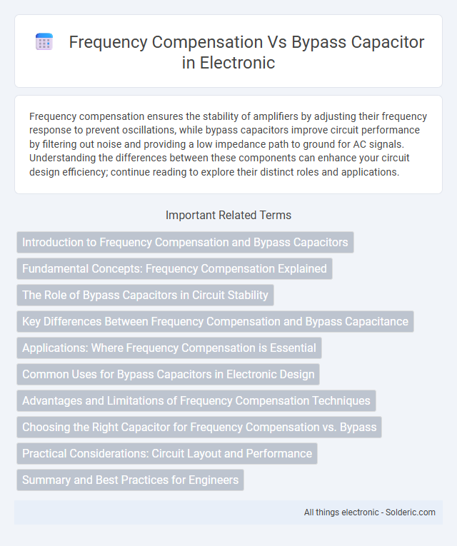
Introduction to Frequency Compensation and Bypass Capacitors
Frequency compensation stabilizes amplifier circuits by controlling the frequency response to prevent oscillations and improve phase margin, crucial in operational amplifiers and feedback systems. Bypass capacitors enhance circuit performance by filtering out noise and stabilizing the power supply voltage, especially in digital and analog circuits. Both frequency compensation and bypass capacitors serve distinct roles in maintaining signal integrity and circuit stability in electronic designs.
Fundamental Concepts: Frequency Compensation Explained
Frequency compensation involves stabilizing an amplifier's frequency response to prevent oscillations by controlling phase margin and gain crossover points. Bypass capacitors, on the other hand, serve to filter noise and stabilize voltage supply by providing a low-impedance path to ground for high-frequency signals. Understanding frequency compensation helps you design circuits that maintain consistent performance across varying frequencies while effectively utilizing bypass capacitors to reduce signal distortion.
The Role of Bypass Capacitors in Circuit Stability
Bypass capacitors play a critical role in circuit stability by filtering out high-frequency noise and providing a low-impedance path to ground for transient currents. This mitigates voltage fluctuations and prevents oscillations, ensuring stable operation of amplifiers and other sensitive components. In contrast to frequency compensation techniques that adjust frequency response, bypass capacitors directly stabilize power supply lines and enhance overall circuit reliability.
Key Differences Between Frequency Compensation and Bypass Capacitance
Frequency compensation involves adding capacitors to control the stability and bandwidth of an amplifier by shaping its frequency response, whereas a bypass capacitor is used primarily to filter out noise and stabilize voltage in power supply lines. Frequency compensation targets the internal feedback loop to prevent oscillations and ensure consistent performance across frequencies, while bypass capacitors provide a low impedance path to ground for high-frequency signals, reducing voltage ripple. Understanding these differences can help you optimize your circuit's stability and signal integrity effectively.
Applications: Where Frequency Compensation is Essential
Frequency compensation is essential in high-frequency amplifier circuits and operational amplifiers to ensure stability and prevent oscillations in feedback loops. This technique is crucial in precision analog signal processing, such as in instrumentation amplifiers and active filters, where maintaining consistent gain and phase margins is necessary. In contrast, bypass capacitors primarily serve to filter noise and stabilize power supply lines rather than control frequency response or stability.
Common Uses for Bypass Capacitors in Electronic Design
Bypass capacitors are commonly used in electronic design to stabilize power supply voltages by filtering out noise and transient voltage spikes, ensuring smooth operation of integrated circuits. Frequency compensation involves components like capacitors configured to optimize the frequency response of amplifiers and prevent oscillations, but bypass capacitors specifically help maintain voltage integrity at high frequencies. Your circuit's performance benefits significantly from strategically placed bypass capacitors that reduce electromagnetic interference and improve signal stability.
Advantages and Limitations of Frequency Compensation Techniques
Frequency compensation techniques enhance amplifier stability and extend bandwidth by controlling gain and phase margin, offering precise adjustments that bypass capacitors cannot achieve. These methods optimize frequency response without adding large reactive components, reducing distortion and power consumption, but may require complex design and increase circuit complexity. Limitations include potential reduction in gain and susceptibility to temperature variations, necessitating careful implementation to balance performance and stability.
Choosing the Right Capacitor for Frequency Compensation vs. Bypass
Choosing the right capacitor for frequency compensation versus bypass applications depends on the specific role each plays in your circuit's stability and noise filtering. Frequency compensation capacitors are selected for their precise capacitance and low leakage to control the amplifier's phase margin and prevent oscillations, often using film or ceramic types with stable dielectric properties. In contrast, bypass capacitors prioritize low equivalent series resistance (ESR) and high-frequency performance to filter power supply noise, typically utilizing ceramic capacitors placed as close as possible to the IC power pins to maintain signal integrity and stable voltage levels.
Practical Considerations: Circuit Layout and Performance
Frequency compensation requires careful placement of components to minimize parasitic inductances and capacitances that can degrade amplifier stability and response, whereas bypass capacitors demand proximity to power pins to reduce supply noise and maintain voltage integrity. Your circuit layout must separate high-frequency compensation paths from sensitive signal traces to prevent interference, while bypass capacitors should be placed near ground return paths to optimize transient response. Proper layout ensures improved gain margins and reduced noise, enhancing overall circuit performance and reliability.
Summary and Best Practices for Engineers
Frequency compensation techniques stabilize amplifier circuits by improving phase margin and preventing oscillations, whereas bypass capacitors enhance power supply integrity by filtering noise and reducing voltage fluctuations. Engineers should carefully select compensation components based on circuit bandwidth and gain requirements, while bypass capacitors must be placed close to IC power pins with appropriate capacitance values for optimal high-frequency noise reduction. Combining proper frequency compensation with well-designed bypass capacitor placement ensures reliable, stable, and high-performance electronic designs.
frequency compensation vs bypass capacitor Infographic