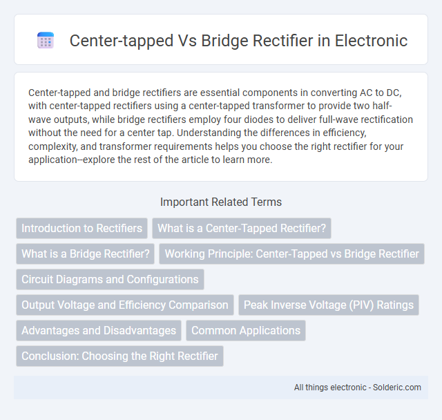
Center-tapped and bridge rectifiers are essential components in converting AC to DC, with center-tapped rectifiers using a center-tapped transformer to provide two half-wave outputs, while bridge rectifiers employ four diodes to deliver full-wave rectification without the need for a center tap. Understanding the differences in efficiency, complexity, and transformer requirements helps you choose the right rectifier for your application--explore the rest of the article to learn more.
Comparison Table
| Feature | Center-Tapped Rectifier | Bridge Rectifier |
|---|---|---|
| Configuration | Uses center-tapped transformer with two diodes | Uses four diodes arranged in a bridge |
| Number of Diodes | Two | Four |
| Transformer Requirement | Center-tapped transformer required | No center-tapped transformer needed |
| Output Voltage | Approximately half transformer secondary voltage | Full transformer secondary voltage minus diode drops |
| Peak Inverse Voltage (PIV) | Twice the peak secondary voltage | Equal to peak secondary voltage |
| Transformer Utilization Factor (TUF) | Lower | Higher |
| Efficiency | Lower due to diode configuration | Higher efficiency |
| Cost | Lower diode cost; higher transformer cost | Higher diode cost; lower transformer cost |
| Complexity | More complex due to transformer | Simpler transformer requirements |
| Application | Used when center-tapped transformer is available | Widely used in power supplies without center-tap |
Introduction to Rectifiers
Rectifiers convert alternating current (AC) into direct current (DC), crucial for powering electronic devices. Center-tapped rectifiers use a transformer with a center tap to provide two equal voltages, enabling full-wave rectification with fewer diodes but a more complex transformer design. Bridge rectifiers employ four diodes arranged in a bridge configuration, offering full-wave rectification without the need for a center-tapped transformer, resulting in better transformer utilization and higher output voltage.
What is a Center-Tapped Rectifier?
A center-tapped rectifier is a type of full-wave rectifier that uses a transformer with a center-tapped secondary winding to convert alternating current (AC) into direct current (DC). It provides two equal voltages with opposite polarities, allowing two diodes to conduct alternately during each half-cycle of the AC input, resulting in a smoother DC output. This configuration requires a center-tapped transformer, making it more complex but efficient for applications needing low ripple voltage.
What is a Bridge Rectifier?
A bridge rectifier is an electronic circuit that converts alternating current (AC) into direct current (DC) using four diodes arranged in a bridge configuration. It provides full-wave rectification, enabling current to flow through the load during both halves of the AC cycle, resulting in higher efficiency compared to center-tapped rectifiers. Your choice of a bridge rectifier ensures better utilization of the transformer and smoother DC output in power supply applications.
Working Principle: Center-Tapped vs Bridge Rectifier
The center-tapped rectifier uses a transformer with a center tap to provide two equal voltages, allowing each diode to conduct during alternate half-cycles, effectively converting AC to pulsating DC. The bridge rectifier employs four diodes arranged in a bridge configuration, enabling full-wave rectification without the need for a center-tapped transformer by directing current through different diode pairs during each half-cycle. Understanding these working principles helps you choose the most efficient rectifier circuit for your power supply design based on transformer availability and output requirements.
Circuit Diagrams and Configurations
Center-tapped rectifier circuits utilize a transformer with a center tap on the secondary winding, enabling two diodes to conduct alternately and produce full-wave rectification with fewer components. In contrast, bridge rectifier configurations employ four diodes arranged in a bridge topology to convert AC to DC without requiring a center-tapped transformer, offering more efficient utilization of the transformer winding. Understanding your specific application's voltage and current requirements helps determine the optimal circuit configuration between center-tapped and bridge rectifiers.
Output Voltage and Efficiency Comparison
Center-tapped rectifiers typically produce an output voltage of about half the input AC voltage per diode, resulting in lower output voltage compared to bridge rectifiers, which use four diodes and provide nearly the full peak input voltage. Bridge rectifiers offer higher efficiency due to better utilization of the transformer winding and reduced voltage drop across fewer diodes conducting at any time. Overall, bridge rectifiers yield higher output voltage and improved efficiency, making them preferable in applications demanding maximum power delivery.
Peak Inverse Voltage (PIV) Ratings
Center-tapped rectifiers experience a Peak Inverse Voltage (PIV) that is equal to twice the peak voltage of the transformer secondary winding, making PIV a critical factor in diode selection and insulation design. Bridge rectifiers, by contrast, have a PIV rating equal to the peak voltage of the transformer secondary, allowing the use of diodes with lower voltage ratings and enabling more efficient utilization of components. Understanding the distinct PIV requirements helps optimize the design for voltage stress, cost, and reliability in power supply circuits.
Advantages and Disadvantages
Center-tapped rectifiers offer the advantage of producing a full-wave output with fewer diodes, which can reduce component costs and simplify design, but require a center-tapped transformer that tends to be bulkier and more expensive. Bridge rectifiers eliminate the need for a center-tapped transformer, allowing use of simpler transformers and providing higher transformer utilization, yet they involve four diodes leading to higher conduction losses and increased power dissipation. Your choice depends on balancing transformer complexity against diode losses and overall circuit requirements for efficiency and cost.
Common Applications
Center-tapped rectifiers are commonly used in power supplies requiring dual voltage output and in audio amplifiers for smooth signal conversion. Bridge rectifiers are widely applied in low voltage, high current applications such as battery charging and DC motor drives due to their efficient full-wave rectification without the need for a center-tapped transformer. Understanding your application's voltage and current needs helps determine the best rectifier configuration for optimal performance.
Conclusion: Choosing the Right Rectifier
Center-tapped rectifiers provide a simpler design for dual voltage outputs and are ideal for low to medium power applications but require a center-tapped transformer, increasing cost and size. Bridge rectifiers offer higher efficiency and power output without needing a center tap, making them suitable for high-current and compact designs. Selecting the right rectifier depends on power requirements, transformer availability, and design constraints, with bridge rectifiers favored for modern applications demanding higher efficiency and lower transformer costs.
center-tapped vs bridge rectifier Infographic