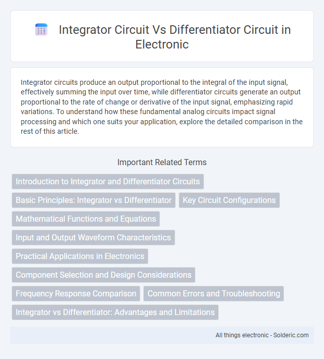
Integrator circuits produce an output proportional to the integral of the input signal, effectively summing the input over time, while differentiator circuits generate an output proportional to the rate of change or derivative of the input signal, emphasizing rapid variations. To understand how these fundamental analog circuits impact signal processing and which one suits your application, explore the detailed comparison in the rest of this article.
Comparison Table
| Feature | Integrator Circuit | Differentiator Circuit |
|---|---|---|
| Primary Function | Calculates the integral of the input signal over time | Calculates the derivative of the input signal with respect to time |
| Output Signal | Proportional to the cumulative sum (integral) of the input | Proportional to the rate of change (derivative) of the input |
| Typical Components | Operational amplifier, resistor, capacitor (in feedback) | Operational amplifier, resistor, capacitor (in series) |
| Frequency Response | Low-pass filter behavior; attenuates high frequencies | High-pass filter behavior; amplifies high frequencies |
| Common Applications | Signal integration, waveform generation, analog computers | Edge detection, signal differentiation, waveform shaping |
| Mathematical Operation | Output Vout = - (1/RC) Vin dt | Output Vout = -RC (dVin/dt) |
| Noise Sensitivity | Less sensitive to high-frequency noise | Highly sensitive to high-frequency noise |
| Design Complexity | Relatively simple design | Requires careful noise management |
Introduction to Integrator and Differentiator Circuits
Integrator circuits perform mathematical integration of input signals, producing an output proportional to the cumulative sum over time, commonly implemented using operational amplifiers with capacitive feedback. Differentiator circuits output the rate of change of the input signal, effectively highlighting rapid variations, typically configured with operational amplifiers incorporating capacitive input and resistive feedback. Both circuits are fundamental in analog signal processing, enabling waveform shaping, signal conditioning, and applications in control systems and real-time analysis.
Basic Principles: Integrator vs Differentiator
An integrator circuit produces an output voltage proportional to the integral of the input signal, effectively summing the input over time, and is typically implemented using an operational amplifier with a capacitor in the feedback loop. A differentiator circuit generates an output voltage proportional to the rate of change or derivative of the input signal, emphasizing rapid transitions and is usually realized by placing a capacitor at the input and a resistor in the feedback path of the op-amp. The fundamental difference lies in the integrator's role in accumulating signal energy versus the differentiator's function in detecting instantaneous changes in the input waveform.
Key Circuit Configurations
Integrator circuits commonly use an operational amplifier with a capacitor placed in the feedback loop and a resistor at the input, enabling the output voltage to represent the integral of the input signal over time. Differentiator circuits typically employ an operational amplifier with a capacitor at the input and a resistor in the feedback path, producing an output voltage proportional to the rate of change of the input signal. These configurations are fundamental in analog signal processing for performing mathematical integration and differentiation, respectively.
Mathematical Functions and Equations
Integrator circuits perform the mathematical integration of input signals, implementing the equation \( V_{out}(t) = -\frac{1}{RC} \int V_{in}(t) dt \), where \( R \) and \( C \) are the resistor and capacitor values respectively. Differentiator circuits execute the differentiation operation, following the equation \( V_{out}(t) = -RC \frac{dV_{in}(t)}{dt} \), emphasizing rapid changes in the input signal. Both circuits use operational amplifiers with specific feedback components to realize these fundamental calculus functions in analog form.
Input and Output Waveform Characteristics
Integrator circuits transform an input waveform, such as a square wave, into a triangular output waveform by accumulating the input signal over time, resulting in a smoothed, ramp-like output. Differentiator circuits produce an output waveform that represents the rate of change of the input signal, converting a ramp or triangular input waveform into sharp pulses or spikes at points of signal transition. The input-output relationship in integrators and differentiators is fundamentally linked to calculus operations, with integrators performing time integration and differentiators executing time differentiation on the input waveform.
Practical Applications in Electronics
Integrator and differentiator circuits play critical roles in analog signal processing, with integrators widely used in analog filters, signal waveform generation, and analog computers for accumulation tasks, while differentiators excel in edge detection, motion sensing, and frequency modulation demodulation. Your choice between these circuits depends on whether you need to measure the area under a signal curve or detect rapid signal changes, essential in control systems and instrumentation. Both circuits are fundamental in shaping signals for communication systems, oscillators, and real-time data analysis applications.
Component Selection and Design Considerations
Integrator circuits typically use capacitors and operational amplifiers, requiring low-leakage capacitors and precision resistors to ensure accurate time integration and minimize drift. Differentiator circuits demand high-quality resistors and capacitors with minimal parasitic effects to accurately track rapid signal changes without amplifying high-frequency noise. Your component selection should prioritize tolerance, frequency response, and stability based on the intended signal processing application for optimal circuit performance.
Frequency Response Comparison
Integrator circuits exhibit a frequency response characterized by attenuation of high-frequency signals, effectively producing an output proportional to the integral of the input, with amplitude decreasing at a rate of 20 dB per decade as frequency increases. Differentiator circuits amplify high-frequency components, generating an output proportional to the derivative of the input signal, showing a gain that increases at 20 dB per decade with frequency. Understanding these contrasting frequency behaviors helps optimize your signal processing tasks, especially in filtering and waveform shaping applications.
Common Errors and Troubleshooting
Integrator circuits often face errors like input bias current causing output drift, while differentiator circuits frequently encounter noise amplification and oscillations due to high-frequency signal components. Troubleshooting integrators involves checking capacitor integrity and minimizing input offset voltage, whereas differentiators require proper resistor selection and adding low-pass filters to stabilize the output. Accurate component values and careful PCB layout reduce errors in both integrator and differentiator circuits, ensuring reliable signal processing.
Integrator vs Differentiator: Advantages and Limitations
Integrator circuits provide the advantage of producing output voltage proportional to the integral of the input signal, enabling applications in signal processing and analog computing, but they are limited by issues such as drift and low-frequency noise. Differentiator circuits offer rapid response by outputting the rate of change of the input signal, making them useful for edge detection and high-frequency signal analysis, yet they face challenges including high sensitivity to noise and instability at high frequencies. Both circuits require careful design considerations to balance accuracy, stability, and noise performance in practical electronic systems.
integrator circuit vs differentiator circuit Infographic