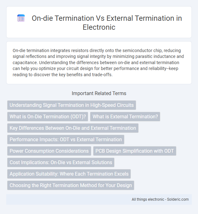
On-die termination integrates resistors directly onto the semiconductor chip, reducing signal reflections and improving signal integrity by minimizing parasitic inductance and capacitance. Understanding the differences between on-die and external termination can help you optimize your circuit design for better performance and reliability--keep reading to discover the key benefits and trade-offs.
Comparison Table
| Feature | On-Die Termination (ODT) | External Termination |
|---|---|---|
| Definition | Termination resistor integrated within the IC die | Termination resistor placed externally on the PCB |
| Signal Integrity | Improves signal quality by reducing reflections directly on-die | Depends on PCB layout; potential for increased parasitic effects |
| Design Complexity | Simplifies board design by eliminating external components | Requires careful PCB design and component placement |
| Power Consumption | Typically lower power due to optimized IC design | May lead to higher power consumption due to resistor heat dissipation |
| Cost | Reduces BOM cost by integrating resistors | Increases BOM cost due to additional components |
| Flexibility | Limited resistance value options, fixed by IC design | Flexible resistor value selection based on design needs |
| Thermal Management | Better due to on-chip heat distribution | Requires PCB heat management for resistors |
| Common Applications | Modern DDR memory interfaces (DDR3, DDR4) | Legacy systems, high-frequency analog signals |
Understanding Signal Termination in High-Speed Circuits
On-die termination (ODT) integrates the termination resistors directly within the integrated circuit, minimizing signal reflections and improving signal integrity at high frequencies. External termination uses discrete resistors placed on the circuit board, allowing flexibility in termination resistance but often introducing parasitic inductance and capacitance that can degrade signal quality. Understanding the trade-offs between ODT and external termination is crucial for optimizing impedance matching, reducing electromagnetic interference, and ensuring reliable data transmission in high-speed digital circuits.
What is On-Die Termination (ODT)?
On-Die Termination (ODT) is a technique used in high-speed memory interfaces where termination resistors are integrated directly within the memory chip to minimize signal reflections and improve signal integrity. This embedded termination reduces the need for external termination components, thereby simplifying the PCB layout and enhancing overall performance in DDR memory systems. Understanding ODT helps you optimize your system for better data stability and reduced electromagnetic interference.
What is External Termination?
External termination refers to the use of resistors or other components placed outside an integrated circuit to match impedance and minimize signal reflections on high-speed communication lines. This technique helps maintain signal integrity by providing proper load termination, especially in systems where on-die termination is insufficient or unavailable. Understanding external termination is essential for optimizing your circuit's performance and ensuring reliable data transmission.
Key Differences Between On-Die and External Termination
On-die termination (ODT) integrates termination resistors directly within the memory chip, reducing signal reflections and improving signal integrity by matching impedance close to the source. External termination uses discrete resistors placed on the motherboard or module, offering flexibility in termination values but increasing board complexity and potential signal degradation. Your choice between ODT and external termination impacts overall system performance, power consumption, and PCB design complexity.
Performance Impacts: ODT vs External Termination
On-die termination (ODT) significantly reduces signal reflections and improves signal integrity by integrating termination resistors directly within the memory chip, resulting in lower latency and enhanced overall performance compared to external termination. External termination, while flexible and adjustable, introduces additional parasitic inductance and capacitance from external components and PCB traces, which can degrade signal quality and increase power consumption. Consequently, ODT offers superior performance impacts in high-speed memory interfaces such as DDR4 and DDR5 by minimizing timing errors and improving data throughput efficiency.
Power Consumption Considerations
On-die termination (ODT) significantly reduces power consumption compared to external termination by minimizing signal reflections directly within the memory chip. External termination requires additional resistors and circuitry on the motherboard, leading to increased power draw and heat dissipation. Optimizing your system with ODT can enhance energy efficiency and thermal management in high-speed memory applications.
PCB Design Simplification with ODT
On-die termination (ODT) integrates resistive termination directly within memory chips, significantly reducing the need for external termination components on the PCB. This integration simplifies PCB design by minimizing trace routing complexity, lowering component count, and decreasing signal reflection issues. As a result, ODT enhances signal integrity and improves overall system reliability while enabling more compact and cost-effective PCB layouts.
Cost Implications: On-Die vs External Solutions
On-die termination (ODT) significantly reduces cost by integrating termination resistors directly onto the semiconductor die, eliminating the need for additional external components and complex PCB routing. External termination solutions, while offering flexibility in tuning impedance, incur higher expenses due to extra resistor components, increased PCB space, and assembly labor costs. Your choice between ODT and external termination should consider system complexity and budget constraints, as ODT offers a cost-efficient, simplified design ideal for high-volume production.
Application Suitability: Where Each Termination Excels
On-die termination (ODT) excels in high-speed memory interfaces such as DDR4 and DDR5, where minimizing signal reflection and reducing power consumption are critical for maintaining data integrity and performance. External termination is better suited for legacy systems or complex multi-drop buses where customizable termination values are necessary to handle diverse load conditions and longer trace lengths. ODT is ideal for compact, high-density designs, while external termination offers flexibility in system-level tuning and troubleshooting.
Choosing the Right Termination Method for Your Design
Choosing the right termination method for your design depends on signal integrity requirements and board layout constraints. On-die termination (ODT) integrates resistors directly within the IC, reducing reflections and simplifying PCB routing, ideal for high-speed memory interfaces like DDR4 and DDR5. External termination offers flexibility in resistor values and placement, beneficial for designs requiring customizable impedance control or where ODT is unavailable.
On-die termination vs external termination Infographic