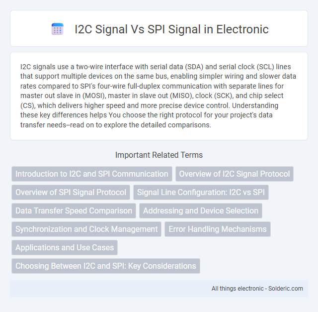
I2C signals use a two-wire interface with serial data (SDA) and serial clock (SCL) lines that support multiple devices on the same bus, enabling simpler wiring and slower data rates compared to SPI's four-wire full-duplex communication with separate lines for master out slave in (MOSI), master in slave out (MISO), clock (SCK), and chip select (CS), which delivers higher speed and more precise device control. Understanding these key differences helps You choose the right protocol for your project's data transfer needs--read on to explore the detailed comparisons.
Comparison Table
| Feature | I2C Signal | SPI Signal |
|---|---|---|
| Communication Type | Serial, half-duplex | Serial, full-duplex |
| Number of Wires | 2 (SDA, SCL) | 4 (MOSI, MISO, SCLK, SS) |
| Speed | Standard up to 400 kbps, Fast up to 3.4 Mbps | Typically 1 Mbps to 50+ Mbps |
| Addressing | Supports multi-device addressing | No addressing, uses chip select signals |
| Signal Lines | Data (SDA), Clock (SCL) | Master Out Slave In (MOSI), Master In Slave Out (MISO), Clock (SCLK), Slave Select (SS) |
| Master/Slave Support | Multi-master and multi-slave | Single master, multiple slaves with separate SS lines |
| Data Transfer | Half-duplex, bidirectional via SDA | Full-duplex, simultaneous send and receive |
| Use Cases | Low-speed sensors, ICs, EEPROMs | High-speed peripherals, ADCs, DACs, displays |
| Signal Integrity | Open-drain with pull-up resistors | Push-pull outputs |
| Complexity | Lower pin count, simpler wiring | More pins, higher speed complexity |
Introduction to I2C and SPI Communication
I2C (Inter-Integrated Circuit) communication utilizes a two-wire interface comprising a serial data line (SDA) and a serial clock line (SCL) for synchronous, multi-master, multi-slave data transfer, ideal for short-distance communication between integrated circuits. SPI (Serial Peripheral Interface) communication employs four wires--MISO, MOSI, SCLK, and SS--for high-speed, full-duplex, point-to-point data exchange, commonly used in applications demanding rapid data throughput. Both protocols serve distinct use cases with I2C offering simpler wiring and addressing multiple devices on a single bus, while SPI provides faster communication and dedicated lines for each slave device.
Overview of I2C Signal Protocol
I2C signal protocol operates with a two-wire communication system consisting of a Serial Data Line (SDA) and a Serial Clock Line (SCL) that allows multiple devices to share the same bus. It uses open-drain or open-collector outputs with pull-up resistors, enabling bidirectional data flow and collision detection through addressing and acknowledgment bits. The protocol supports standard (100 kbps), fast (400 kbps), and high-speed (3.4 Mbps) modes, providing efficient, low-pin-count communication ideal for short-distance, intra-board connections.
Overview of SPI Signal Protocol
SPI signal protocol operates as a synchronous serial communication interface using separate lines for data (MOSI and MISO), clock (SCLK), and chip select (CS) signals, enabling full-duplex data transfer. Its clock-driven data exchange allows higher speed and greater data throughput compared to I2C, which uses only two lines (SDA and SCL) for half-duplex communication. SPI's dedicated chip select lines enable multiple slave devices to communicate independently with a single master, making it ideal for applications requiring high-speed and low-latency data transmission.
Signal Line Configuration: I2C vs SPI
I2C uses two signal lines, SDA (Serial Data) and SCL (Serial Clock), enabling bidirectional communication and allowing multiple devices to share the same bus through addressing. SPI operates with four lines: MOSI (Master Out Slave In), MISO (Master In Slave Out), SCLK (Serial Clock), and SS (Slave Select), providing separate data channels for full-duplex communication. Your choice between I2C and SPI depends on the balance between simplicity and communication speed or complexity in device connections.
Data Transfer Speed Comparison
I2C signals typically operate at speeds up to 3.4 Mbps with standard modes like Fast-mode Plus, making them suitable for moderate-speed communication in sensor and control applications. SPI signals can reach much higher data transfer speeds, often exceeding 50 Mbps, due to their full-duplex capability and dedicated clock lines. Your choice between I2C and SPI should consider the required data throughput and complexity of wiring for optimal performance.
Addressing and Device Selection
I2C signals utilize a unique 7-bit or 10-bit addressing scheme embedded in the data frame to identify and communicate with multiple devices on the same bus, enabling simple device selection using a single shared clock (SCL) and data (SDA) line. SPI signals, in contrast, rely on separate chip select (CS) lines for each device, requiring individual pins for device selection, which allows for faster communication but increases wiring complexity. The addressing in I2C facilitates multi-master and multi-slave configurations with fewer pins, while SPI's hardware-driven device selection offers lower protocol overhead and higher data throughput.
Synchronization and Clock Management
I2C communication employs a single shared clock line (SCL) generated by the master device to synchronize data transfer between multiple slaves, ensuring coordinated timing across all connected devices. SPI uses separate clock (SCK) and data lines with clock management exclusively controlled by the master, allowing full-duplex communication and higher data rates through precise timing and flexible clock phase/polarity configurations. The synchronization in I2C relies on open-drain lines with pull-up resistors, enabling multi-master arbitration, whereas SPI's push-pull drivers provide dedicated timing stability but lack built-in collision detection.
Error Handling Mechanisms
I2C uses an acknowledgment (ACK/NACK) bit after every byte to detect errors such as missing acknowledgments, enabling quick retransmission or termination of communication. SPI lacks built-in error detection, relying on higher-layer protocols for error handling and data integrity verification. The presence of an ACK mechanism in I2C enhances fault detection during data transfer, while SPI's simplicity requires external methods for error management.
Applications and Use Cases
I2C signals are widely used for short-distance communication in embedded systems, sensor interfacing, and low-speed data exchange due to their simple two-wire design and multi-master capability. SPI signals excel in high-speed data transfer applications such as flash memory communication, display modules, and real-time data acquisition systems, benefiting from full-duplex communication and separate clock and data lines. Both I2C and SPI protocols enable efficient peripheral integration, with I2C preferred for complex bus configurations and SPI favored for speed-critical use cases.
Choosing Between I2C and SPI: Key Considerations
Choosing between I2C and SPI depends on factors like communication speed, complexity, and device count. I2C supports multiple devices on a two-wire bus with built-in addressing, making it ideal for simpler, slower connections up to 400 kbps or 1 Mbps in fast mode. SPI offers higher speeds, up to tens of Mbps, with separate lines for data and clock, making it preferable for applications requiring rapid data transfer and reduced latency in your embedded systems.
I2C signal vs SPI signal Infographic