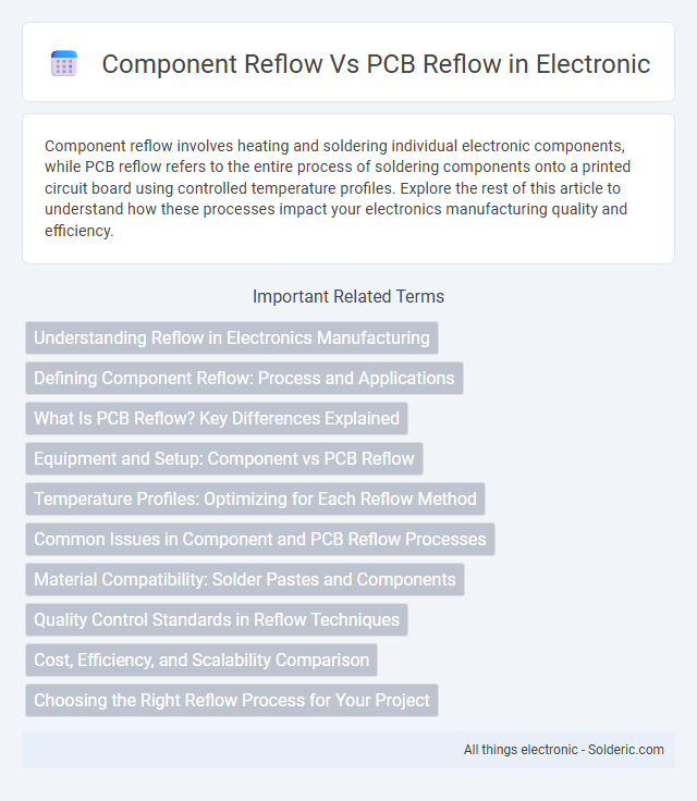
Component reflow involves heating and soldering individual electronic components, while PCB reflow refers to the entire process of soldering components onto a printed circuit board using controlled temperature profiles. Explore the rest of this article to understand how these processes impact your electronics manufacturing quality and efficiency.
Comparison Table
| Aspect | Component Reflow | PCB Reflow |
|---|---|---|
| Definition | Heating process to solder components onto a PCB | Heating process to solder multiple components simultaneously on the PCB |
| Scope | Single or few components | Entire PCB assembly |
| Process Type | Localized, manual or selective | Automated, batch reflow oven process |
| Temperature Profile | Targeted heat application, variable profiles | Controlled, predefined thermal profile for entire PCB |
| Typical Usage | Repairs, small production runs, prototyping | Mass production, standard assembly lines |
| Equipment | Hot air station, soldering iron, or selective reflow tools | Reflow oven with conveyor system |
| Efficiency | Lower throughput, higher precision | High throughput, consistent quality |
| Cost | Lower initial cost, higher labor cost | Higher initial investment, lower per-unit cost |
Understanding Reflow in Electronics Manufacturing
Reflow in electronics manufacturing involves melting solder to securely attach components to PCBs, with Component reflow focusing on accurately placing individual parts while PCB reflow ensures the entire board undergoes uniform heating for reliable connections. Precise temperature control and timing during PCB reflow prevent damage to sensitive components while achieving consistent solder joints. Understanding the differences in these processes helps optimize Your assembly line for quality and efficiency.
Defining Component Reflow: Process and Applications
Component reflow refers to the precise heating process used to melt solder paste and attach electronic components onto printed circuit boards (PCBs) with optimal mechanical and electrical connections. This process involves controlled temperature profiles tailored to specific component types, ensuring proper solder joint formation without damaging sensitive parts. Widely applied in surface-mount technology (SMT) assembly, component reflow is critical for achieving reliable functionality in high-density electronic devices.
What Is PCB Reflow? Key Differences Explained
PCB reflow is the process of heating a printed circuit board to melt and solidify solder paste, ensuring secure electrical connections between electronic components and the PCB surface. Component reflow refers to heating individual components during assembly, while PCB reflow involves heating the entire board to simultaneously bond all components. Key differences include scale, process control, and thermal profiling, where PCB reflow requires precise temperature management to prevent damage and achieve optimal solder joints across diverse components.
Equipment and Setup: Component vs PCB Reflow
Component reflow typically requires precise soldering equipment such as soldering irons, reflow ovens, or hot air stations tailored for individual or small batches of components, ensuring accurate thermal profiles for diverse part sizes. PCB reflow involves a more complex setup with conveyorized reflow ovens designed to uniformly heat entire boards, enabling simultaneous soldering of multiple surface-mount devices while maintaining consistent temperature zones. Your choice of equipment impacts production efficiency, thermal control, and solder joint quality in both processes.
Temperature Profiles: Optimizing for Each Reflow Method
Temperature profiles for component reflow prioritize precise heating to prevent damage to delicate electronic parts, with controlled ramp-up and cool-down rates tailored to component specifications. PCB reflow temperature profiles emphasize uniform heat distribution across the entire board to ensure proper solder joint formation without warping or thermal stress. Optimizing these profiles involves balancing peak temperature, soak time, and cooling rates based on the thermal mass and sensitivity of components versus the larger PCB assembly.
Common Issues in Component and PCB Reflow Processes
Common issues in component reflow include tombstoning, where one end of a component lifts due to uneven solder wetting, and solder bridging caused by excessive solder paste or misaligned components. PCB reflow problems often involve warping from uneven heat distribution and insufficient solder joint formation due to inadequate temperature profiles. Both processes can suffer from voiding in solder joints, leading to reliability concerns in electronic assemblies.
Material Compatibility: Solder Pastes and Components
Material compatibility between solder pastes and components is critical during both component reflow and PCB reflow processes to ensure reliable solder joints. Solder pastes must match the thermal profiles and chemical properties suitable for the specific component materials, such as preventing damage to sensitive chips or avoiding corrosion on metallic leads. Selecting compatible solder paste flux types and compositions minimizes defects like cold solder joints or component warping, optimizing assembly quality and long-term performance.
Quality Control Standards in Reflow Techniques
Quality control standards in component reflow emphasize precise temperature profiling to ensure solder joints meet reliability criteria, minimizing defects such as cold solder or bridging. PCB reflow standards incorporate comprehensive inspection methods like X-ray and AOI (Automated Optical Inspection) to guarantee alignment and solder integrity across complex board assemblies. You can improve manufacturing consistency by adhering to IPC standards that regulate both component and PCB reflow processes for optimal quality assurance.
Cost, Efficiency, and Scalability Comparison
Component reflow involves soldering individual electronic parts onto a PCB, typically resulting in lower upfront costs but higher labor intensity and longer processing times compared to PCB reflow, which uses automated ovens for simultaneous soldering of all components, enhancing efficiency and scalability. PCB reflow offers better uniformity and reduces errors in mass production, making it more cost-effective at scale despite higher initial equipment investment. For large-volume manufacturing, PCB reflow provides superior scalability and consistent quality, whereas component reflow remains more suitable for prototyping or small-batch runs due to its flexibility and lower immediate expenses.
Choosing the Right Reflow Process for Your Project
Selecting the right reflow process depends on component sensitivity and PCB complexity; component reflow targets individual parts, ideal for prototypes or small runs, while PCB reflow suits full assemblies, ensuring uniform soldering of all components simultaneously. Consider thermal profiles and assembly scale to optimize solder joint quality and minimize thermal stress on delicate components. Employing appropriate reflow techniques directly impacts reliability, production efficiency, and overall project success in electronics manufacturing.
Component reflow vs PCB reflow Infographic