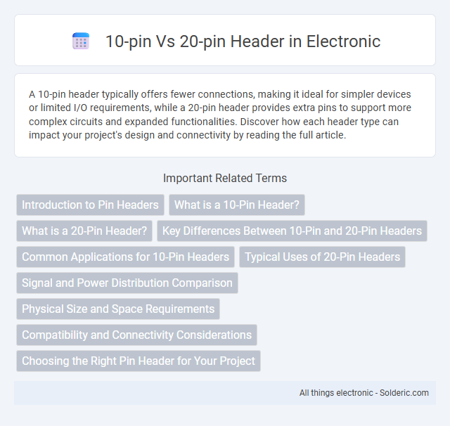
A 10-pin header typically offers fewer connections, making it ideal for simpler devices or limited I/O requirements, while a 20-pin header provides extra pins to support more complex circuits and expanded functionalities. Discover how each header type can impact your project's design and connectivity by reading the full article.
Comparison Table
| Feature | 10-Pin Header | 20-Pin Header |
|---|---|---|
| Pin Count | 10 Pins | 20 Pins |
| Use Case | Basic connectivity, simple signals | Complex devices, multiple signals |
| Data Transfer | Limited bandwidth | Higher bandwidth support |
| Size | Smaller footprint | Larger footprint |
| Pin Spacing | Standard 2.54mm (0.1 inch) | Standard 2.54mm (0.1 inch) |
| Compatibility | Common in basic microcontroller boards | Used in advanced peripherals and expansion |
| Signal Types | Power, ground, simple I/O | Power, ground, multiple I/O lines, control signals |
Introduction to Pin Headers
Pin headers serve as essential connectors on PCBs, enabling communication between various components. A 10-pin header offers a compact interface with limited connections, ideal for simple circuits or signal transmissions. In contrast, a 20-pin header provides increased connectivity and flexibility, supporting more complex functions and additional power or data lines in electronic designs.
What is a 10-Pin Header?
A 10-pin header is a small electronic connector with 10 pins arranged in a single or dual row, commonly used to interface internal components such as sensors, displays, or peripherals on printed circuit boards (PCBs). It provides a compact and reliable means of establishing electrical connections while maintaining signal integrity and simplifying assembly or troubleshooting. Choosing the appropriate header depends on your device's pin count and connectivity requirements, where 10-pin headers are ideal for moderate complexity compared to larger 20-pin headers.
What is a 20-Pin Header?
A 20-pin header is a type of electrical connector commonly used in computer motherboards and electronic devices to facilitate data and power transmission. It features 20 individual pins arranged in two rows, enabling multiple simultaneous connections for components such as front panel connectors, USB ports, or sensors. Compared to 10-pin headers, the 20-pin design provides greater connectivity options and supports more complex interfacing requirements.
Key Differences Between 10-Pin and 20-Pin Headers
10-pin headers typically provide a more compact interface for simpler connections, often used in smaller electronics or limited space environments, while 20-pin headers offer expanded connectivity options suited for complex systems requiring more signal or power lines. The 20-pin header's additional pins allow for increased data transfer, multiple power rails, or combined functions like I2C and SPI interfaces, enabling more flexible circuit designs. Pin spacing and physical size also differ, with 20-pin headers usually having a larger footprint, influencing PCB layout and connector compatibility.
Common Applications for 10-Pin Headers
10-pin headers are commonly used in programming and debugging interfaces for microcontrollers such as ARM Cortex and AVR devices, providing connections for JTAG or SWD protocols. These headers support compact and efficient data transfer, making them ideal for embedded system development and prototype testing. In contrast, 20-pin headers often serve more complex communication needs or power delivery, but 10-pin headers remain the standard for many low-pin-count applications requiring precise signal control.
Typical Uses of 20-Pin Headers
20-pin headers are commonly used in more complex electronic devices requiring multiple signal and power connections, such as motherboards, development boards, and communication devices. They facilitate extensive data transfer and power delivery between components, supporting advanced functionalities and peripheral integration. Compared to 10-pin headers, 20-pin headers offer greater pin density, enabling more sophisticated circuit designs and enhanced connectivity options.
Signal and Power Distribution Comparison
A 10-pin header typically supports fewer signal and power lines, limiting its capacity to handle complex circuits or devices requiring multiple connections. In contrast, a 20-pin header allows enhanced signal distribution and higher power supply capabilities, offering more channels for communication and increased current delivery. The larger pin count in a 20-pin header reduces signal interference and voltage drops by segregating power and ground lines more effectively.
Physical Size and Space Requirements
A 10-pin header occupies less physical space on a PCB compared to a 20-pin header, making it ideal for compact designs where minimizing board real estate is crucial. The 20-pin header, with twice the number of pins, requires more area and can increase the overall size of your electronic assembly. When choosing between the two, consider your device's space constraints and the number of connections needed to ensure optimal layout efficiency.
Compatibility and Connectivity Considerations
10-pin headers offer limited connectivity options with fewer signal lines, making them suitable for simpler devices and basic communication protocols like I2C and SPI. 20-pin headers provide enhanced compatibility for complex applications by supporting additional power, ground, and data lines, enabling multiple interfaces and extended functionality. When designing or selecting components, assessing the required pin count is crucial to ensure proper electrical connections and compatibility with target hardware configurations.
Choosing the Right Pin Header for Your Project
Selecting the appropriate pin header depends on the complexity of your circuit and signal requirements; a 10-pin header is ideal for compact designs with fewer connections, while a 20-pin header supports more extensive data transfer and additional power lines. Consider the spacing between pins and compatibility with existing components to ensure reliable connectivity and ease of assembly. Evaluating current capacity, signal integrity, and physical constraints will guide the optimal choice between a 10-pin and 20-pin header for your electronics project.
10-pin vs 20-pin header Infographic