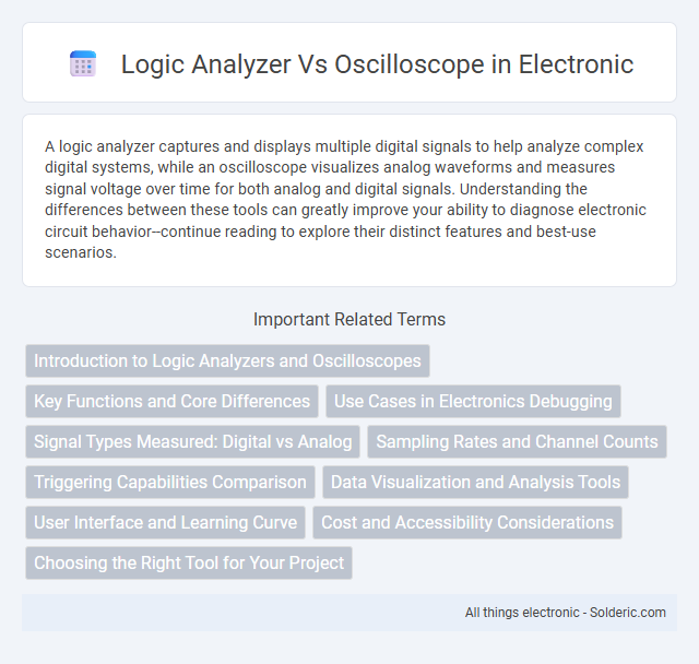
A logic analyzer captures and displays multiple digital signals to help analyze complex digital systems, while an oscilloscope visualizes analog waveforms and measures signal voltage over time for both analog and digital signals. Understanding the differences between these tools can greatly improve your ability to diagnose electronic circuit behavior--continue reading to explore their distinct features and best-use scenarios.
Comparison Table
| Feature | Logic Analyzer | Oscilloscope |
|---|---|---|
| Purpose | Captures and analyzes digital signals and logic states | Displays and measures analog and digital waveforms |
| Signal Type | Digital (binary data) | Analog and Digital |
| Channels | Typically 8 to 136 channels | Usually 2 to 4 channels |
| Sampling Rate | Up to hundreds of MHz | Up to several GHz |
| Time Resolution | High digital timing accuracy | Very high temporal resolution of analog signals |
| Use Case | Debugging digital circuits, protocol analysis | Analyzing signal integrity, analog circuit testing |
| Data Storage | Large memory for long digital captures | Moderate memory, focusing on waveform display |
| Display | State tables, timing diagrams | Waveform graphs |
| Cost | Generally lower cost for multi-channel digital analysis | Higher cost for high bandwidth analog capabilities |
Introduction to Logic Analyzers and Oscilloscopes
Logic analyzers capture and display multiple digital signal states over time, enabling detailed analysis of complex digital circuits and protocols. Oscilloscopes visualize analog waveforms and voltage changes, providing real-time insight into signal behavior and timing characteristics. Both tools are essential in electronics testing, with logic analyzers excelling in digital logic debugging and oscilloscopes in examining analog signals.
Key Functions and Core Differences
Logic analyzers capture and analyze multiple digital signals simultaneously, focusing on timing relationships and protocol decoding for complex digital circuits. Oscilloscopes visualize analog waveforms in real-time, measuring voltage variations and signal integrity with high bandwidth and resolution. The core difference lies in the logic analyzer's ability to handle numerous digital channels and interpret digital data streams, while oscilloscopes provide detailed analog signal analysis and waveform visualization.
Use Cases in Electronics Debugging
Logic analyzers excel in debugging complex digital circuits by capturing and analyzing multiple digital signals simultaneously, making them ideal for verifying communication protocols and timing relationships. Oscilloscopes provide detailed waveform visualization of analog signals, essential for identifying voltage levels, signal integrity issues, and transient events in both analog and digital systems. Combining both tools enhances efficiency in electronics debugging by addressing diverse signal characteristics and timing requirements.
Signal Types Measured: Digital vs Analog
Logic analyzers specialize in capturing and analyzing digital signals, making them ideal for debugging complex digital circuits by displaying multiple channels of binary data simultaneously. Oscilloscopes measure analog signals, providing a detailed visualization of voltage waveforms over time, essential for observing signal amplitude, frequency, and noise characteristics. Your choice depends on whether you need to analyze digital logic states or the analog behavior of electronic signals.
Sampling Rates and Channel Counts
Logic analyzers typically feature high channel counts, often ranging from 16 to over 100 channels, enabling simultaneous monitoring of multiple digital signals, while oscilloscopes usually offer fewer channels, commonly 2 to 4, optimized for analog signal analysis. Sampling rates in oscilloscopes are generally higher, exceeding several gigasamples per second (GS/s), providing detailed waveform resolution, whereas logic analyzers operate at lower sampling rates, typically in the range of hundreds of megasamples per second (MS/s), sufficient for digital state capture. The choice between these tools depends on application needs: high channel count and digital signal timing for logic analyzers versus higher sampling resolution for analog waveform inspection in oscilloscopes.
Triggering Capabilities Comparison
Logic analyzers offer advanced triggering capabilities by allowing complex state-based triggers across multiple digital signals simultaneously, enabling precise capture of specific data sequences or protocol events. Oscilloscopes provide versatile triggering options such as edge, pulse width, and pattern triggers primarily focused on analog and mixed-signal waveforms, facilitating real-time visualization of voltage changes. While oscilloscopes excel in detailed waveform analysis with flexible trigger conditions, logic analyzers excel in capturing timing relationships and digital protocol behaviors with more sophisticated multi-signal triggers.
Data Visualization and Analysis Tools
Logic analyzers offer advanced data visualization and analysis tools that capture and display multiple digital signals simultaneously, providing timing diagrams, protocol decoding, and state analysis for complex digital systems. Oscilloscopes provide high-resolution waveform displays suited for analog signal inspection, featuring tools like FFT analysis, cursors, and automatic measurements for signal integrity and troubleshooting. Together, these instruments complement each other in debugging and verifying electronic circuits with comprehensive visual and analytical capabilities.
User Interface and Learning Curve
Logic analyzers feature complex user interfaces with numerous channels and protocol decoding tools, which may require substantial time to master, especially for beginners. Oscilloscopes offer more intuitive, visual waveform displays that are easier for users to interpret quickly, reducing the learning curve significantly. Your choice depends on whether you prioritize detailed digital signal analysis or straightforward analog waveform observation.
Cost and Accessibility Considerations
Logic analyzers generally come at a higher cost compared to oscilloscopes due to their advanced digital signal processing capabilities and multi-channel inputs. Oscilloscopes are more accessible for hobbyists and entry-level engineers, offering a wide range of affordable models suitable for basic analog and digital waveform visualization. Budget-conscious professionals often choose oscilloscopes for cost-effective troubleshooting, while specialized digital circuit analysis may justify the expense of a logic analyzer.
Choosing the Right Tool for Your Project
Logic analyzers excel in capturing and analyzing digital signals across multiple channels, making them ideal for debugging complex microcontroller or digital communication systems. Oscilloscopes provide detailed analog waveform visualization, crucial for troubleshooting signal integrity, voltage levels, and timing in both analog and mixed-signal circuits. Selecting the right tool depends on your project's signal type and diagnostic needs, with logic analyzers suited for digital protocol analysis and oscilloscopes better for analog signal inspection.
Logic analyzer vs Oscilloscope Infographic